First Arduino Foray
Introduction
So back after a week on holiday in sunny Lanzarote and first time using a computer since I left! Batteries fully recharged and ready for some new challenges.
Embedded systems and using software to control the physical environment is something I have been interested in for a long time, weather it is a system to control water levels in an irrigation system, control systems for industry and automotive, robotics or anything else which uses micro-controllers I find very interesting and had always wanted to get more knowledge of.
Last week I picked up a brand new Rasperry Pi 3 and a Arduino UNO. Both of which
are toys I have been meaning to have a play around with for a very long time!
I’ll leave the Pi for the topic of another post and this article is to be all about
the Arduino board. So with that let’s dive in!
The UNO
The Arduino UNO is a popular board for starting out with Arduino and embedded micro-controllers. It has 14 digital pins (6 with PWM) and 6 analog pins.
In this article I couldn’t find a 14 pin female header to represent the digital IO pins on the Arduino, so I have settled for a 13 pin header to represent the pins on the Arduino.
Illumination
First of all, I’m not experienced with electronics or electrical engineering in the slightest. I expect my projects will have inefficient circuits or maybe some that could even be considered unsafe, in this instance tell me on twitter and let’s fix it.
That being said, let’s have a look at the first circuit I built; a simple traffic light system. As most if not all will know, British traffic lights use the following rules:
- Green for (x) seconds
- Amber for (y) seconds
- Red for (x) seconds
- Red & Amber for (y) seconds
- Repeat
A lot of people have already written (much better) how to articles for this project one example being This One or even This One
I thought this would be a pretty easy project to replicate as it only needs 3 LEDs and a resistor (LEDs have very little resistance so we need to protect the Arduino from receiving full current through it’s IO pins). So let’s try and write some code for this:
/*
 * W3s7ys Traffic Lights.
 *
 * light_delay on green
 * 1.5 Sec amber
 * light_delay Red
 * 1.5 Sec red/amber
 * Repeat...
 */

 const int red_pin = 11;
 const int amber_pin = 10;
 const int green_pin = 9;
 const int light_delay = 5000;

void setup() {
  pinMode(red_pin, OUTPUT);
  pinMode(amber_pin, OUTPUT);
  pinMode(green_pin, OUTPUT);
}

void loop() {
  // Turn green pin on.
  digitalWrite(red_pin, LOW);
  digitalWrite(amber_pin, LOW);
  digitalWrite(green_pin, HIGH);

  // wait
  delay(light_delay);

  // turn off the green LED, turn on the amber LED.
  digitalWrite(green_pin, LOW);
  digitalWrite(amber_pin, HIGH);

  // Small delay
  delay(1500);

  // Turn off the amber LED, turn on red.
  digitalWrite(amber_pin, LOW);
  digitalWrite(red_pin, HIGH);

  // another small delay
  delay(light_delay);

  // turn on the amber LED (red is already on)
  digitalWrite(amber_pin, HIGH);

  // Wait...
  delay(1500);
}
After a little experimentation I found that the pinMode() setup commands are
not required as pins are always initialized as output pins anyway. I have
decided to keep them in however for the sake of completeness.
Schematic
Now that you have seen the code, lets see the wiring diagram: N.B. I currently use Eagle for doing electrical schematic and board design. It’s recommended by a number of makers and so I’m using it too!
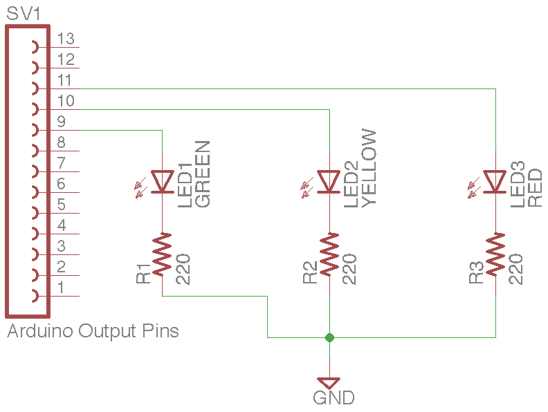
I hope the diagram is self explanatory, the female pin header on the left is representing the digital output header on the UNO board, with wires plugged intro pins 9 (green), 10 (amber) and 11 (red) as defined in the code. All -ve ends of the LEDS (short leads) are connected to a 220 Ohm resistor which is then connected to the GND pin on the Arduino board.
Putting it together
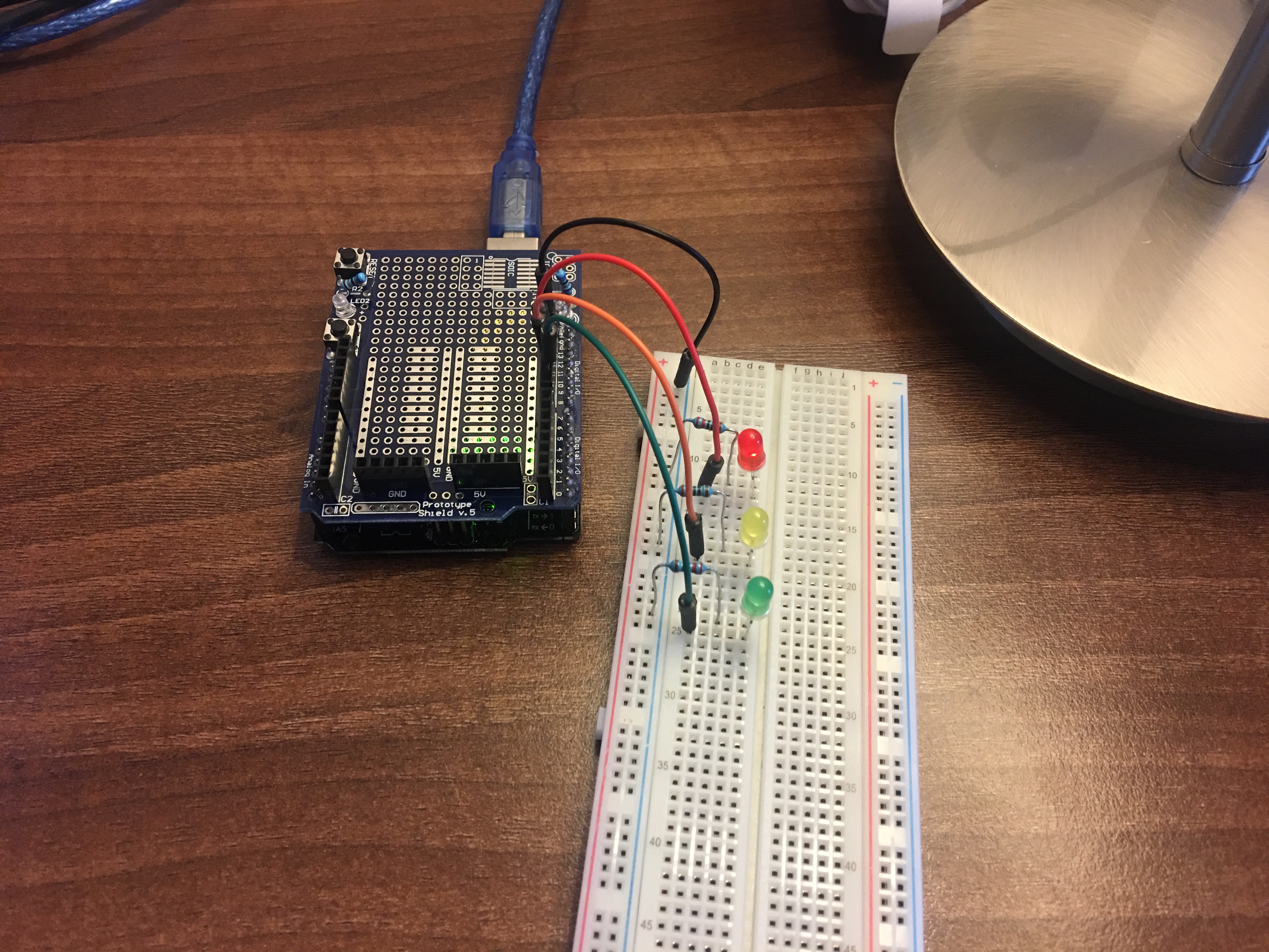
I used a breadboard to put the prototype together, n.b. I’m using the prototype shield for the UNO however this is purely for the additional +5V and GND rails which it provides. You can easily do this without one, just put the GND cable into the GND power pin on the board.
Basic setup
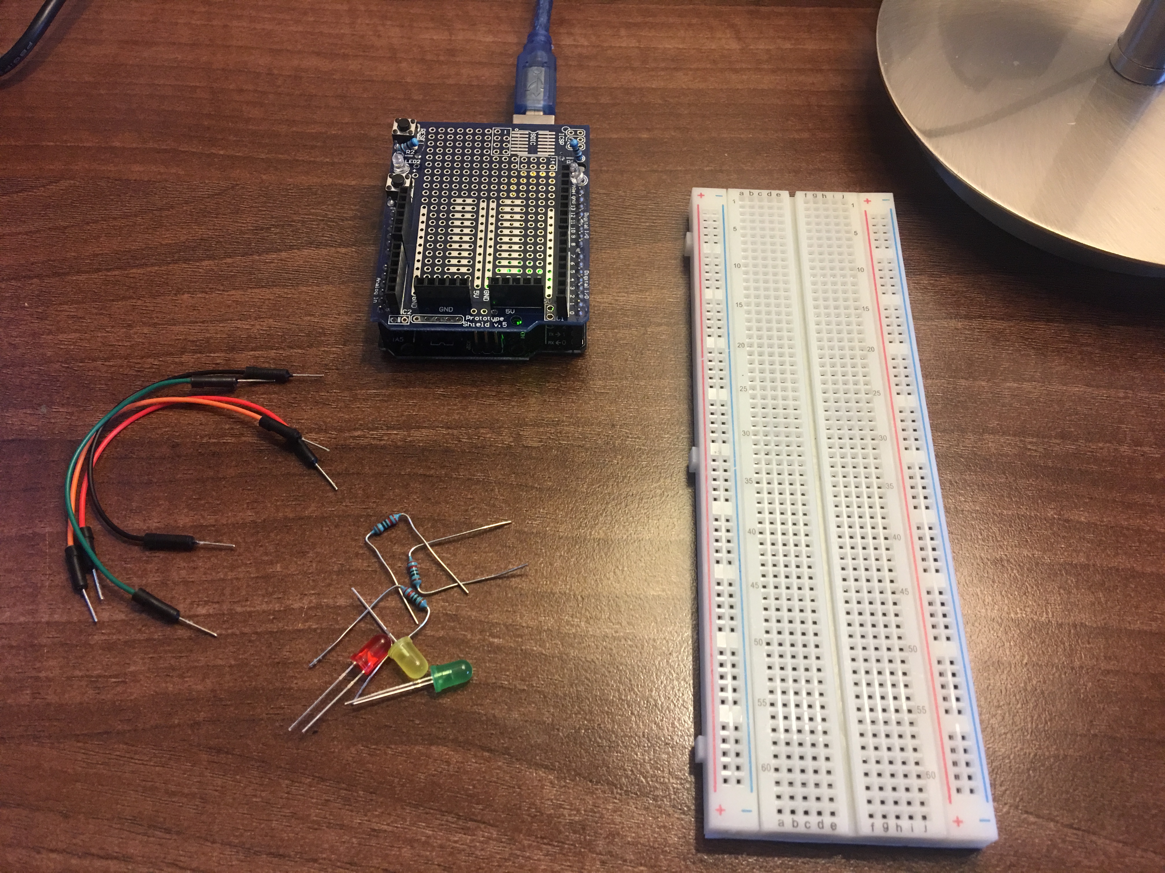
Here is my basic setup, the Arduino is plugged into my Pi via the blue USB cable which provides it’s power and the interface for loading the sketch into the micro-controller chip. Breadboard also in-place alongside the Arduino on the digital IO side.
Note: the prototype shield sat on top of the Arduino board.
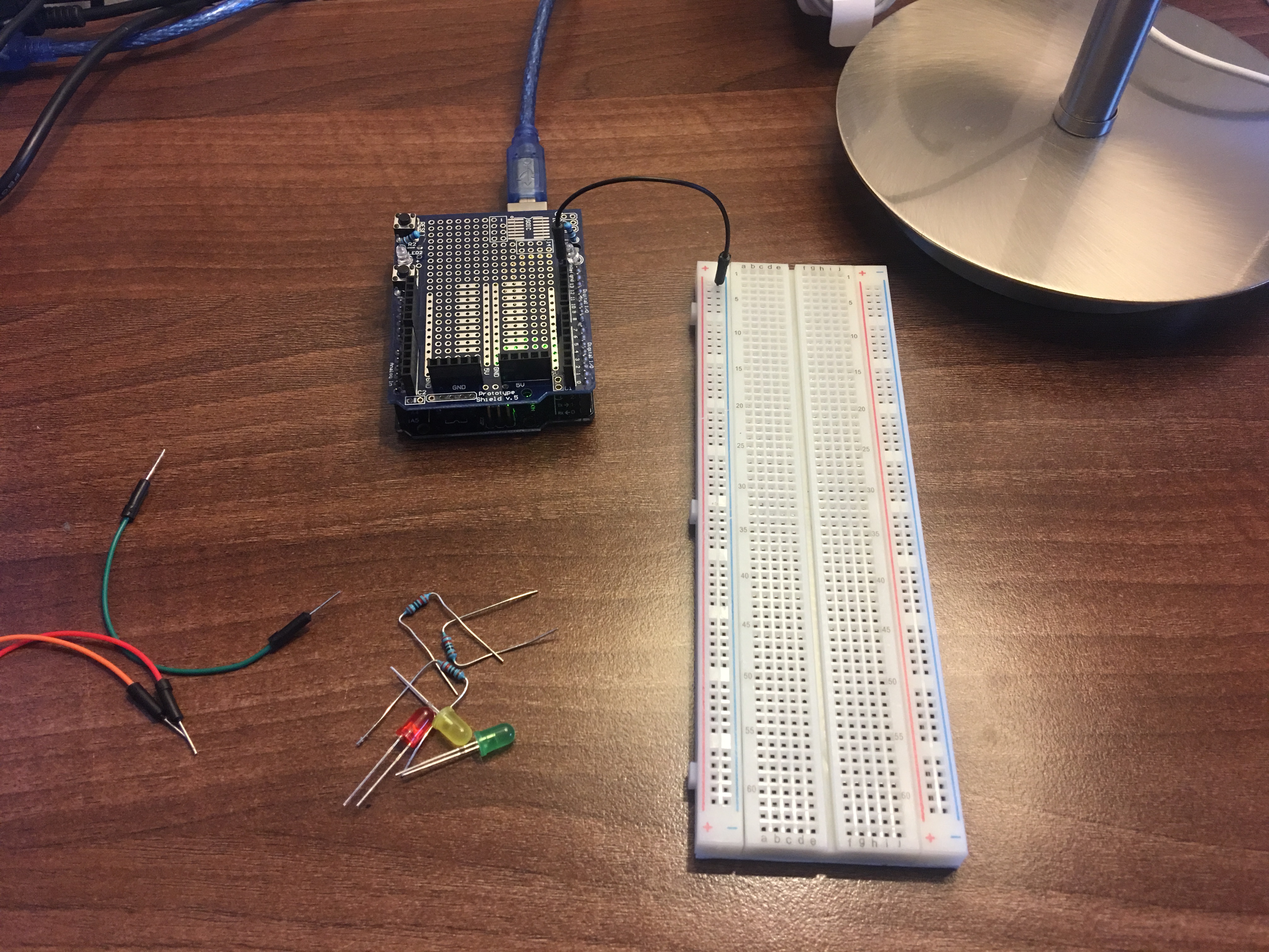
Connecting GND on the breadboard
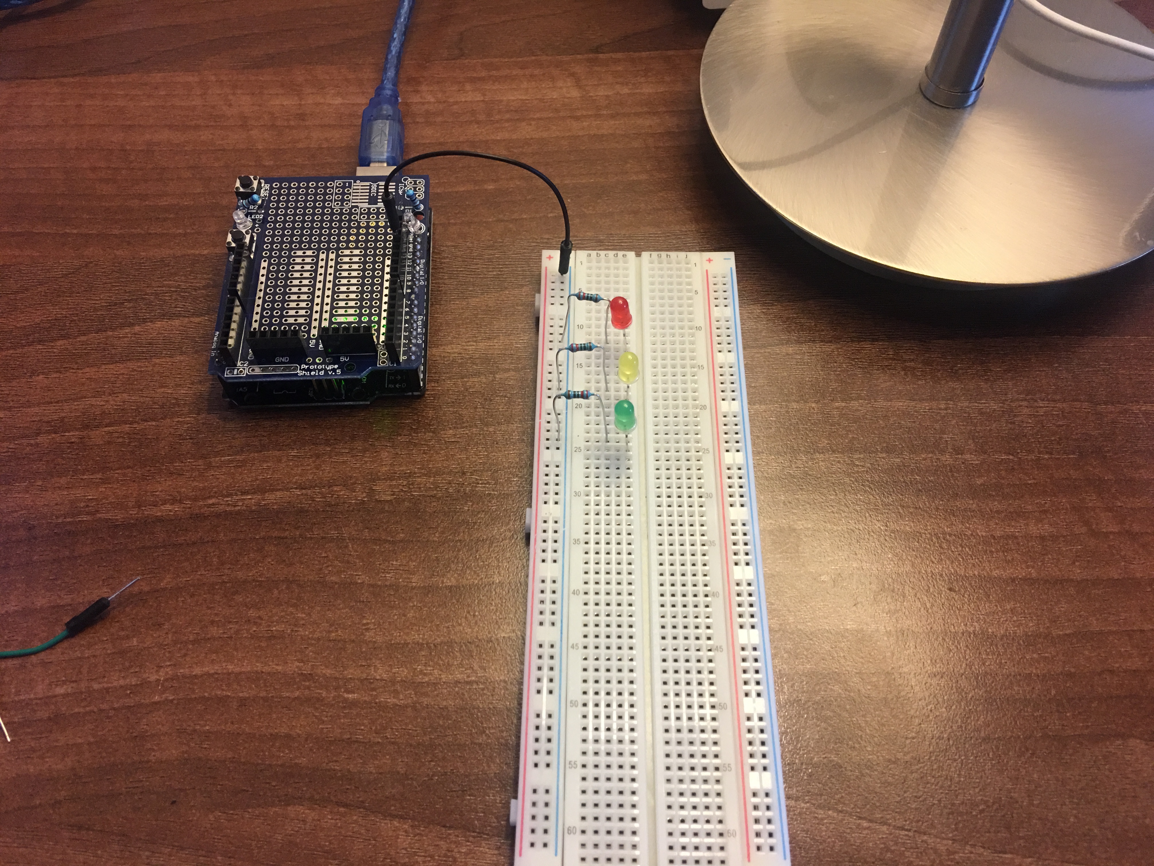
Adding components
Powering up
Conclusion
I thoroughly enjoyed this little project, as I have mentioned earlier I am not from an electrical background. This helped to show me some basics such as digital IO, Ohms law and general electrical prototyping using a breadboard. I know for anyone even slightly versed in electrical engineering this was probably laughable, but I didn’t want to run before I walk so expect probably some more simplistic Arduino projects before we even get slightly complicated!

