Building an oscilloscope
Introduction
First of all let me say sorry for the big delay in getting another blog post out to the wild. It’s certainly not for lacking anything interesting to write about! So for this article first a bit of background, for anyone who isn’t new to this blog will know that I have recently taken up a bit of an interest in electrical engineering. a.k.a. making cool little projects with Arduino boards!
Like most, I already had a multimeter laying around that has already come in useful for measuring resistors (It’s easier than reading the bands on them), checking the output of voltage dividers etc. However there is one piece of ‘bench’ equipment that I see being used time and time again and have always wanted one; the oscilloscope (or just ‘scope’). This allows you to connect to an electronic circuit and ‘see’ the electrical signal at the point you are measuring. E.g. A pulse width modulation (PWM) output on an Arduino board doesn’t actually output a variable voltage (analog) signal. It is a digital pin and only has two states, on or off (or high and low). What the Arduino does to fake an analog signal is instead switch the pin on and off very quickly in order to emulate an analog signal.
In order to ‘see’ this going on you need an oscilloscope, unfortunately most ‘bench’ scopes are around £350 new. Not something a spare time beginner is really going to invest in! (Maybe one day).
Enter the world of DIY
So while browsing Amazon for a job lot of transistors, caps and resistors I found this DIY oscilloscope kit for £20! The kit contains a printed circuit board, LCD display panel and a bag full of components for self assembly. I have (or should say had) never soldered anything in my life at this point and was a little apprehensive about how difficult it might be. But at this price I thought it was worth giving it a go (at least if I cocked it up spectacularly it would only be £20 down the drain). So I went for it, ordered one and a soldering iron, mat, solder etc. etc.
Build day
So all the parts were picked up in the week and Saturday was to be my build day. I got my desk cleared of all the other junk which could catch fire with a hot iron around and setup a good place to sit and work. After getting all the components out of the bag I instantly thought “About 100 components to solder to a PCB, first time soldering… I’m gonna mess this up somewhere”. However after reading through the instructions a few times and practicing my soldering on some spare components and an old PCB from a wireless speaker I felt I was ready for a crack at it. I tested all of the resistors values and pushed them through a piece of A4 paper which I had labelled with the values for quick identification, and counted out the rest of the parts and put them into piles.
I won’t bore with the details (or cringeworthy pictures of my soldering efforts) but suffice to say soldering is actually not too difficult once you get the hang of the amount of time to keep the iron on the joint before plying it with solder. I actually found it quite therapeutic to build stuff on a PCB. Yes there were one or two bits where I laid too much solder on and had to remove it and a few more spots where I maybe melted the PCB slightly (this is what I was most afraid of, knackering the tracks on the PCB with the iron). But I quickly found speed is your friend and the less time the irons tip is near your plastic PCB generally the better! After about 3 hours (with numerous breaks and taking my time) I was all done.
Finished Article (minus the LCD display):

Shot of the back (and some terrible soldering):

Once the components were soldered to the board I ran through the build test steps which involved powering up the unit and testing voltages on a few test points on the PCB and then soldering up a few junctions once the tests were complete. Surprisingly all the tests passed and I was shocked to see the LCD churn into life and present me with an oscilloscope display.
Testing and using the scope
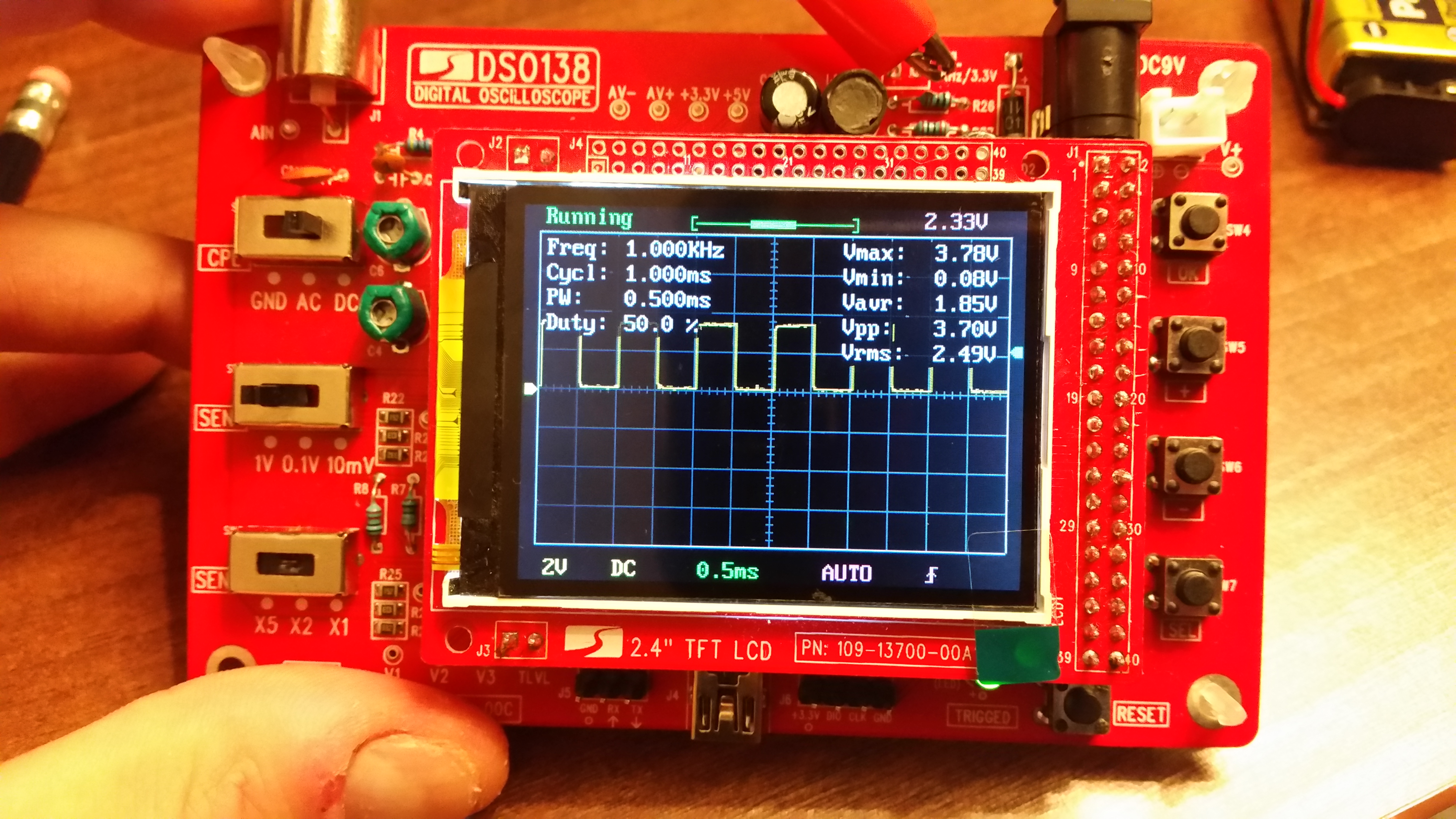
Once I had built the scope I set to giving it a few tests, luckily the scope itself has a ‘test ring’ on the board which you can clip the probe to in order to test functionality. This is a 1Khz square wave at 3.3V with a 50% duty cycle. In other words: The signal is on (3.3V) for X amount of time, then off for X amount of time (i.e. it’s on 50% of the time), with X usually being in the order of milliseconds.
After one initial crap it moment where the screen went blank and nothing seemed to work I tested the voltage of the 9V smoke alarm battery I was using… 6V… ah that’ll do it! After finding a new battery for it we were back in business (that reminds me, I should probably put a new battery in that!)
Clipping up to the test ring we can see the square wave on the display:

As a bit of fun, I wrote some simple Arduino code which would just output different duty cycles on one of the PWM outputs with a delay in between each so I could see if the scope would work on a “real” output.
The Code
void setup() {
  pinMode(3, OUTPUT);
}

void loop() {
  analogWrite(3, 0);
  delay(5000);
  analogWrite(3, 64);
  delay(5000);
  analogWrite(3, 128);
  delay(5000);
  analogWrite(3, 192);
  delay(5000);
  analogWrite(3, 255);
  delay(5000);
}
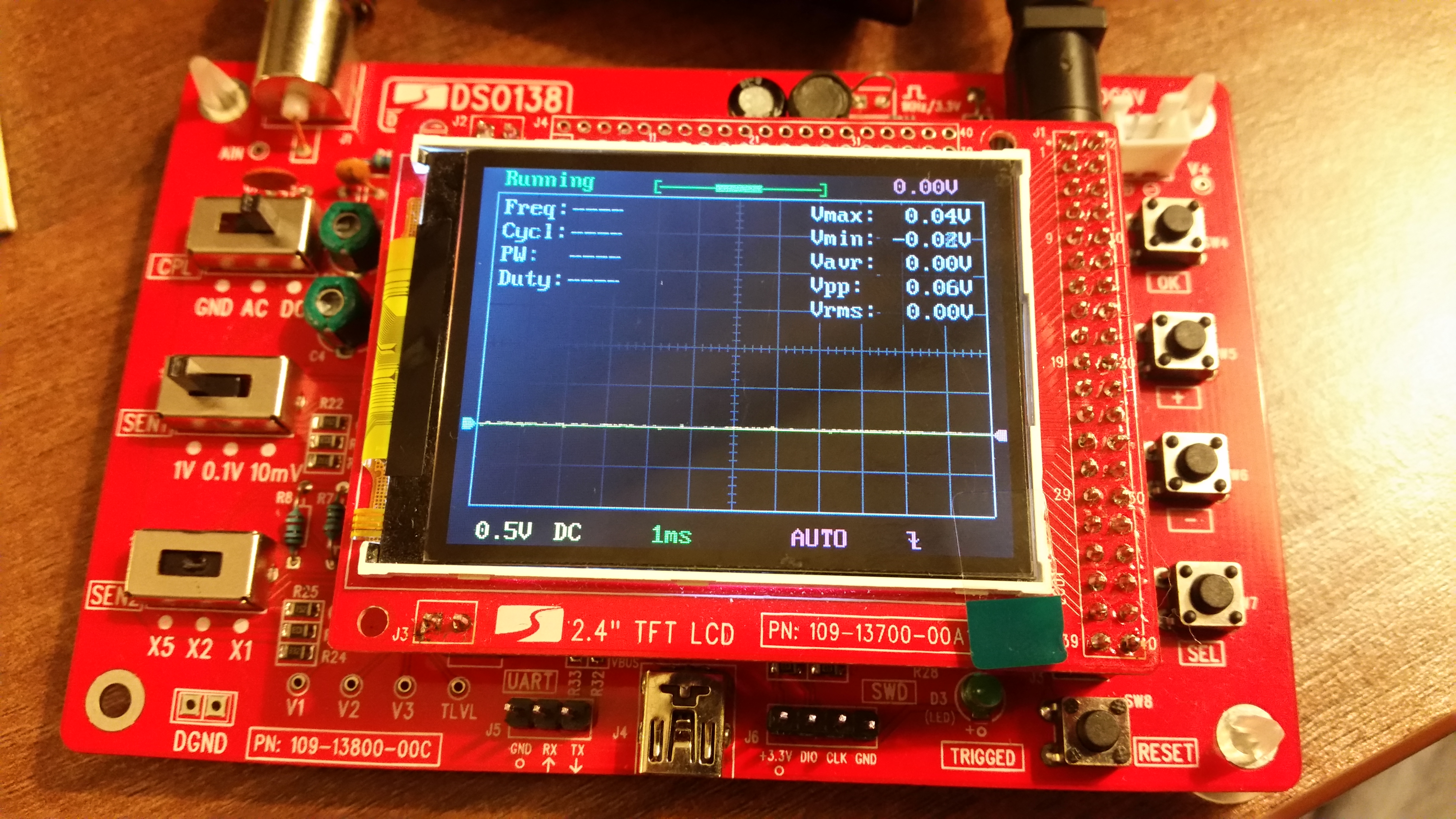
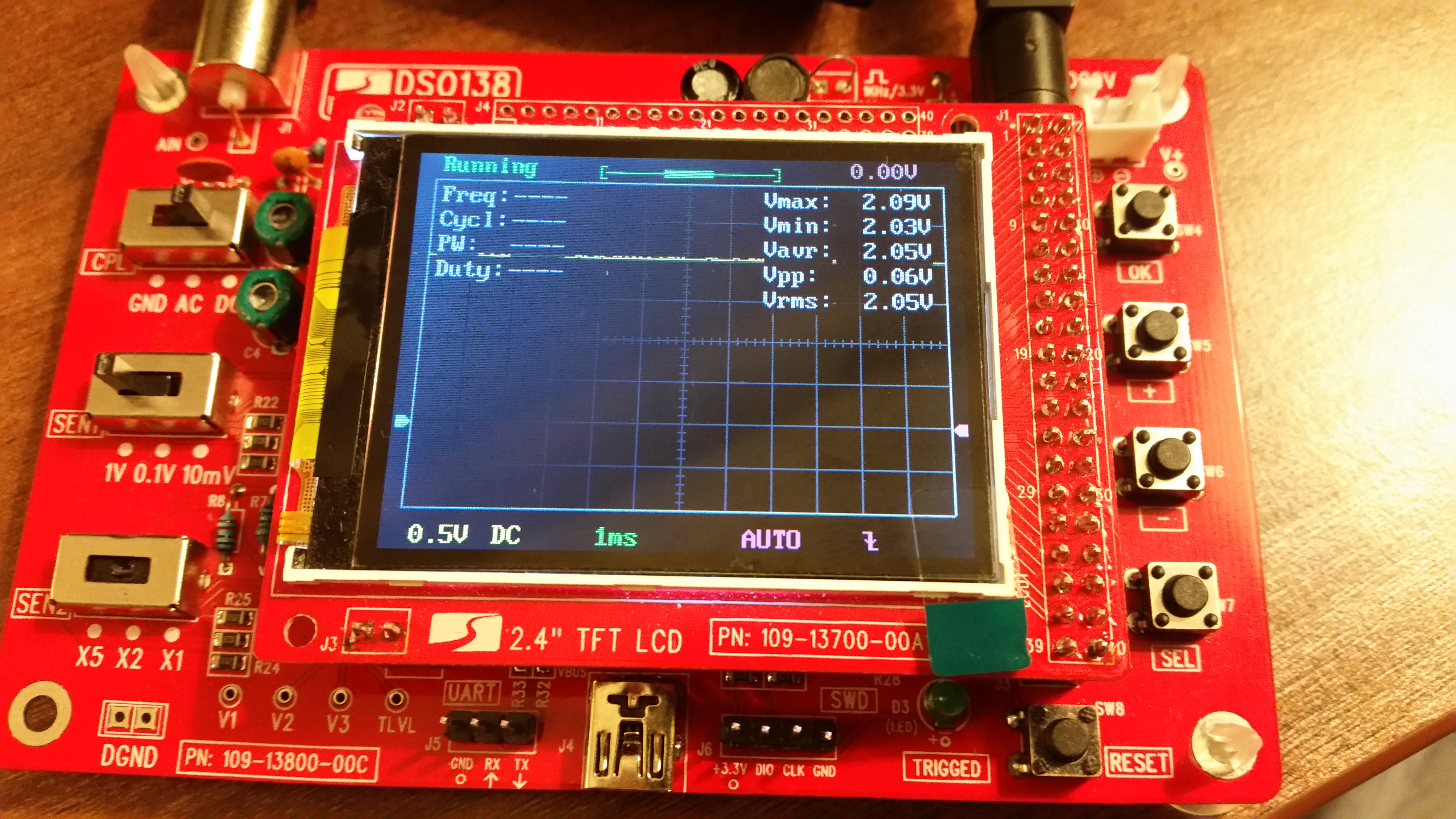
All it does is starting at 0% duty (0), increases by 25% every 5 seconds until at 100% duty (255). I setup an LED with resistor as the test circuit and attached the scope probes either side like this: IMAGE
Here is the output seen on the scope:
Running LOW (0 output)

Running 25% (64 output)

Running 50% (128 output)

Running 75% (192 output)

Running HIGH (255 output)

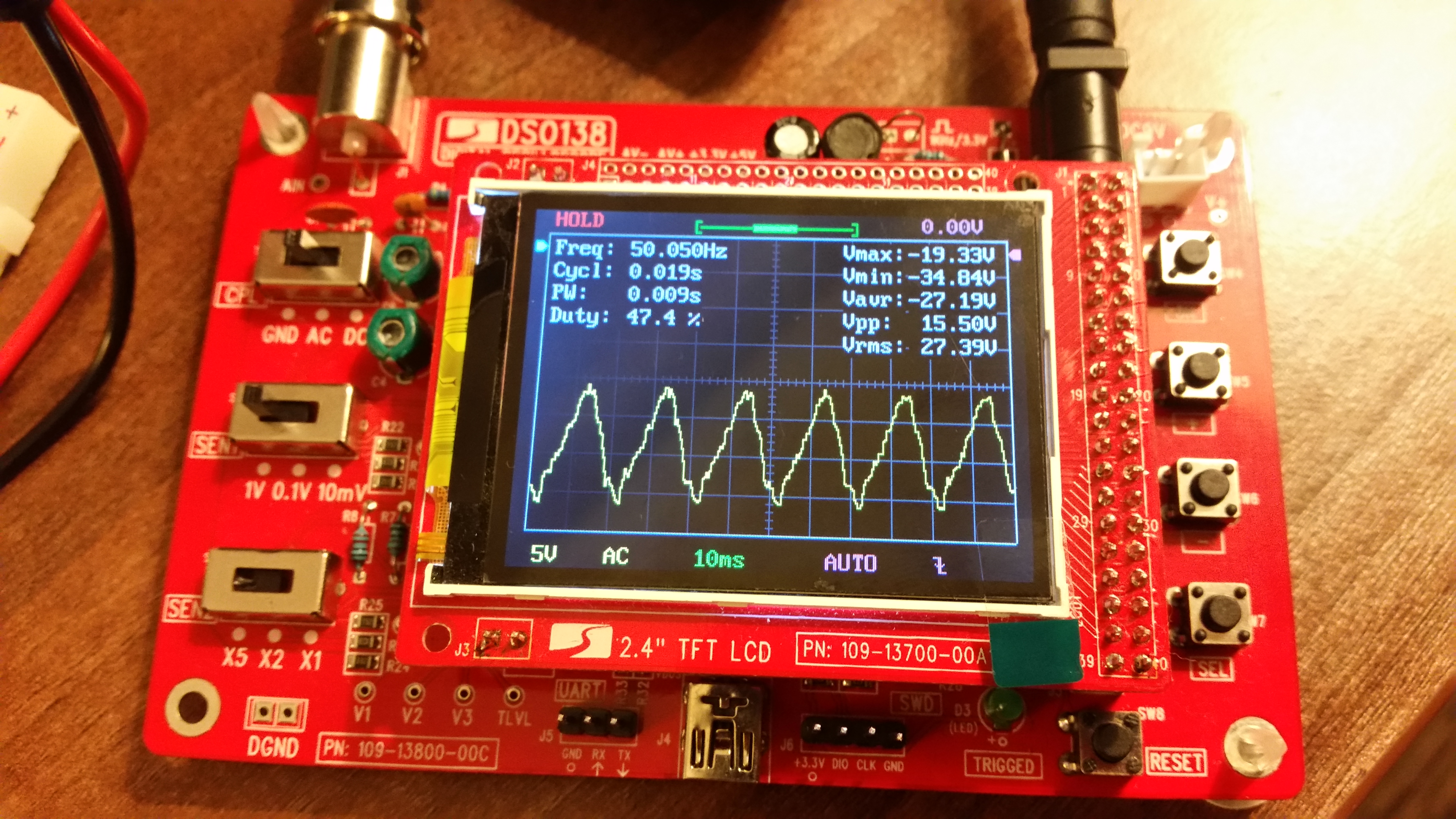
Just for some more fun, I tried powering my Arduino from my USB slot on my MAC which was subsequently plugged into the mains via it’s charging cord. Grounding out the scope on the GND rail and then touching the probe you can even see the 50Hz sine wave resonating from the mains, through my laptop, out of the USB bus and into me!

Conclusion
Great success! I’m honestly amazed I didn’t cook the PCB with the soldering iron
and that I now have an oscilloscope for £20! This is probably not a great scope
for any serious electronic work but for just measuring PWM outputs on an Arduino
it seems to work great! Since building it I went onto YouTube and found a lot of
makers and electricians echoing my sentiments (if your just doing Arduino stuff it’s
a great little tool, but for serious work you really need a bench scope). Now I can
‘see’ electric as it travels through circuits and this doesn’t stop with just PWM.
We can use this to visualise sound signals, data transmission (probably a stretch
for this particular scope) and many other cool things.
